
- #L298N MOTOR DRIVER ARDUINO HOW TO#
- #L298N MOTOR DRIVER ARDUINO CODE#
- #L298N MOTOR DRIVER ARDUINO SERIES#
Hope you understood the DC Motor control using Arduino and L298N Motor Driver.

#L298N MOTOR DRIVER ARDUINO CODE#
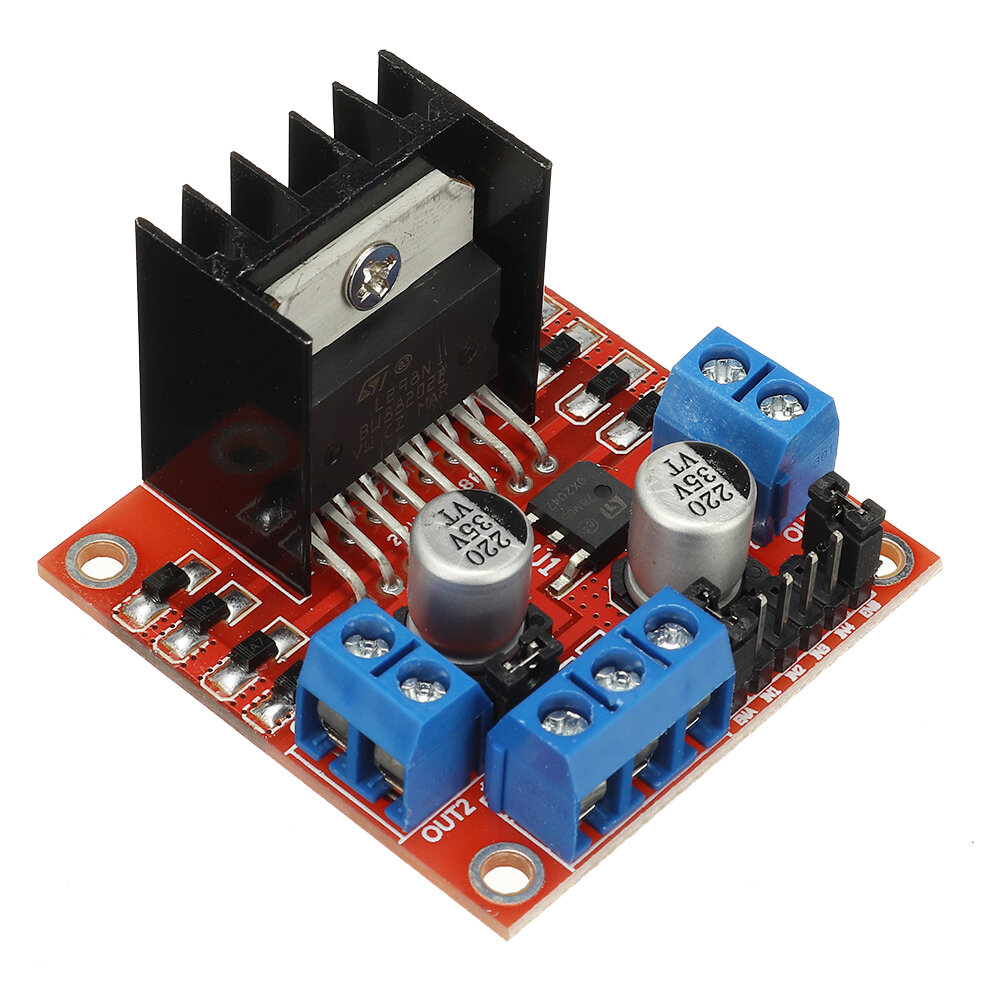
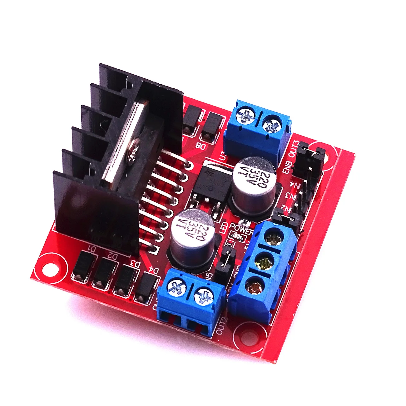
For Anti Clock-wise motion - IN1 = LOW, IN2 = HIGHįor more understanding of control of two DC motors, the arduino code is given below: // connect motor controller pins to Arduino digital pins DC Motor control using Arduino and L298N Motor Driver L298N Truth Table for motor control Arduino Interfacing of 2 DC motors Interfacing DC motors with Arduino Arduino Code If you want to control the speed of motors, you need to remove the jumpers and connect them to PWM-enabled pins on Arduino. When this jumper is in place, the motor is enabled and spins at maximum speed. The module usually comes with a jumper on these pins. Speed Control Pins: ENA and ENB are used to turn the motors ON, OFF and control its speed. Output Pins: The L298N motor driver’s output channels for the motor A and B are broken out to the edge of the module with two 3.5mm-pitch screw terminals.ĭirection Control Pins: The IN1 and IN2 pins control the direction of the motor A while IN3 and IN4 control the direction of the motor B. Note!! : if the motor power supply is greater than 12V, you should remove the jumper to avoid the on-board 5V regulator from getting damaged.Also DO NOT supply power to both the motor power supply input and 5V power supply input when jumper is in place. And they both sink to a common ground named ‘GND’. ‘ Vss’ is used for driving the logic circuitry which can be 5 to 7V. Power Supply: From ‘ Vs’ pin the H-Bridge gets its power for driving the motors which can be 5 to 35V.
#L298N MOTOR DRIVER ARDUINO SERIES#
PWM – For controlling speed: PWM is a technique where average value of the input voltage is adjusted by sending a series of On/OFF pulses, the average voltage is proportional to the width of the pulses known as Duty Cycle.The higher the duty cycle, the greater the average voltage applied to the dc motor this lead to the highest speed. Motor B: This terminal block will give the output for the second motor.ĥV linear Regulator: This will step down the supply voltage to 5V and will give the output at the 5V pin. These will help in controlling the rotation and speed of DC motors. Logic Pins: Connect the Logic pins to any digital pins of Arduino. Keeping the jumper on these pins means that the these pins will be High. If you want to control the stepper motor with L298N, then keep the jumper on Enable A and Enable B. 5V pin will act as Output if the Vs will be less than 12V and 5V pin will act as Input if the Vs will be greater than 12V.Įnable Pins: Remove the jumpers on the Enable A and Enable B if you want to control the speed of DC motors and connect these to PWM pins of Arduino. If your supply voltage is greater than 12, then make sure to remove the 12V jumper. Power Pins: Give the supply voltage from 5 to 35V at the 12V pin and ground. If the supply voltage is greater than 12V, then remove this jumper and give the 5V supply to the 5V power pin so that the L298 Dual H Bridge IC can work properly. The L298N H-bridge module can be used with motors that have a. This allows you to control the speed and direction of two DC motors, or control one bipolar stepper motor with ease.
#L298N MOTOR DRIVER ARDUINO HOW TO#
If you supply high pulse to both IN1 and IN2, then it will act as brake and your motor will stop rotating.Motor A: This terminal block will give the output for the first motor.ġ2V Jumper: Keep this jumper in place if your supply voltage is less than 12V and the 5V power pin will give you the output of 5V. Tutorial -L298N Dual Motor Controller Module 2A and Arduino In this tutorial well explain how to use our L298N H-bridge Dual Motor Controller Module 2A with Arduino. If you supply low pulse to IN1 and high pulse to IN2, then your motor will rotate in reverse direction. The module is build to work on two inputs for each motor, if you power up the circuit and supply high pulse to IN1 and low pulse to IN2, then your motor will rotate in forward direction. It can drive motors from 2v to 10v with zero standby current.

It also equipped with built-in thermal protection and automatic restore function.

It can drive up to two dc motors or a 4-wire steeper motor, can be operate to change the motor direction and speed using PWM. This module is tiny and efficient to drive dc motors up to 2.5A without external heat sink.


 0 kommentar(er)
